Stepper motors are crucial components in various applications, from 3D printers to industrial machinery. Their precise control and reliability make them an ideal choice for many technological systems. At the heart of controlling a stepper motor is the stepper motor driver—a device that plays a pivotal role in ensuring accurate performance. In this article, we’ll explore the essentials of stepper motor drivers, including their functionality, wiring methods, and how they integrate with modern communication protocols like Modbus.
We’ll begin by delving into what a stepper motor driver is and why it’s fundamental for motor control. Next, we’ll break down how a stepper motor driver works, highlighting the mechanisms behind its operation. Following that, we’ll cover stepper motor driver wiring, providing practical guidance on how to connect these drivers effectively. Finally, we’ll examine the use of stepper motor drivers with Modbus, a popular communication protocol that enhances the versatility of stepper motor systems.
By the end of this guide, you’ll have a comprehensive understanding of stepper motor drivers, from their basic functions to advanced integration techniques. Whether you’re a hobbyist or a professional, this article will equip you with the knowledge to optimize your stepper motor setups.
Understanding the Stepper Motor Driver
A stepper motor driver is a critical component in the realm of motor control systems. It serves as the intermediary between a stepper motor and the control signals that direct its movement. Essentially, the stepper motor driver translates electrical pulses into precise mechanical movements, enabling the motor to move in discrete steps. This precise control is what makes stepper motors ideal for applications requiring exact positioning and rotation.
The primary function of a stepper motor driver is to manage the electrical power supplied to the stepper motor. It converts the input signals, typically from a microcontroller or computer, into a series of pulses that drive the motor’s coils. By varying the sequence and frequency of these pulses, the driver controls the speed, direction, and position of the motor. This allows for accurate and repeatable movements, which are essential for tasks like 3D printing, CNC machining, and robotics.
Stepper motor drivers come in various types, including unipolar and bipolar drivers, each suited to different kinds of stepper motors and applications. Unipolar drivers are generally simpler and are often used in less demanding applications, while bipolar drivers offer greater torque and efficiency, making them suitable for more complex and high-performance tasks.
Understanding how a stepper motor driver operates is crucial for anyone working with stepper motors. The driver’s ability to handle pulse signals and its capacity to control current flow to the motor’s coils directly impact the motor’s performance. Hence, choosing the right stepper motor driver for your specific application can significantly influence the efficiency and precision of your system.
In summary, a stepper motor driver is a key component that enables the precise control of stepper motors. By converting electrical signals into mechanical movements, it ensures accurate and reliable operation in various applications.
How Does a Stepper Motor Driver Work?
To fully grasp the role of a stepper motor driver, it’s essential to understand its operational principles. At its core, a stepper motor driver is designed to manage the electrical pulses that control a stepper motor’s movement. This chapter will explain the fundamental workings of a stepper motor driver, including its key components and how they interact to achieve precise motor control.
A stepper motor driver operates by receiving control signals from a microcontroller or other controlling device. These signals are typically in the form of pulse trains. Each pulse represents a step, and the sequence of these pulses dictates the motor’s movement. The driver converts these pulses into electrical currents that energize the motor’s coils, causing the motor to rotate incrementally.
The stepper motor driver’s primary components include a pulse generator, a current driver, and a feedback mechanism. The pulse generator creates the sequence of pulses needed for the motor’s steps. This sequence determines the speed and direction of the motor. The current driver manages the electrical current flowing through the motor coils, ensuring that the motor receives the correct amount of power for each step.
Another important feature is the current control system within the driver. This system regulates the current supplied to the motor to prevent overheating and ensure smooth operation. By adjusting the current dynamically based on load conditions, the driver can maintain optimal performance and extend the motor’s lifespan.
In addition to these components, many stepper motor drivers include microstepping capabilities. Microstepping allows the driver to divide each full step into smaller steps, providing finer resolution and smoother motion. This feature is particularly useful in applications requiring high precision and minimal vibration.
Overall, a stepper motor driver works by converting control signals into precise electrical pulses, managing current flow, and often incorporating advanced features like microstepping. This complex interplay of components and functions ensures that the stepper motor operates with accuracy and reliability, meeting the demands of various applications.
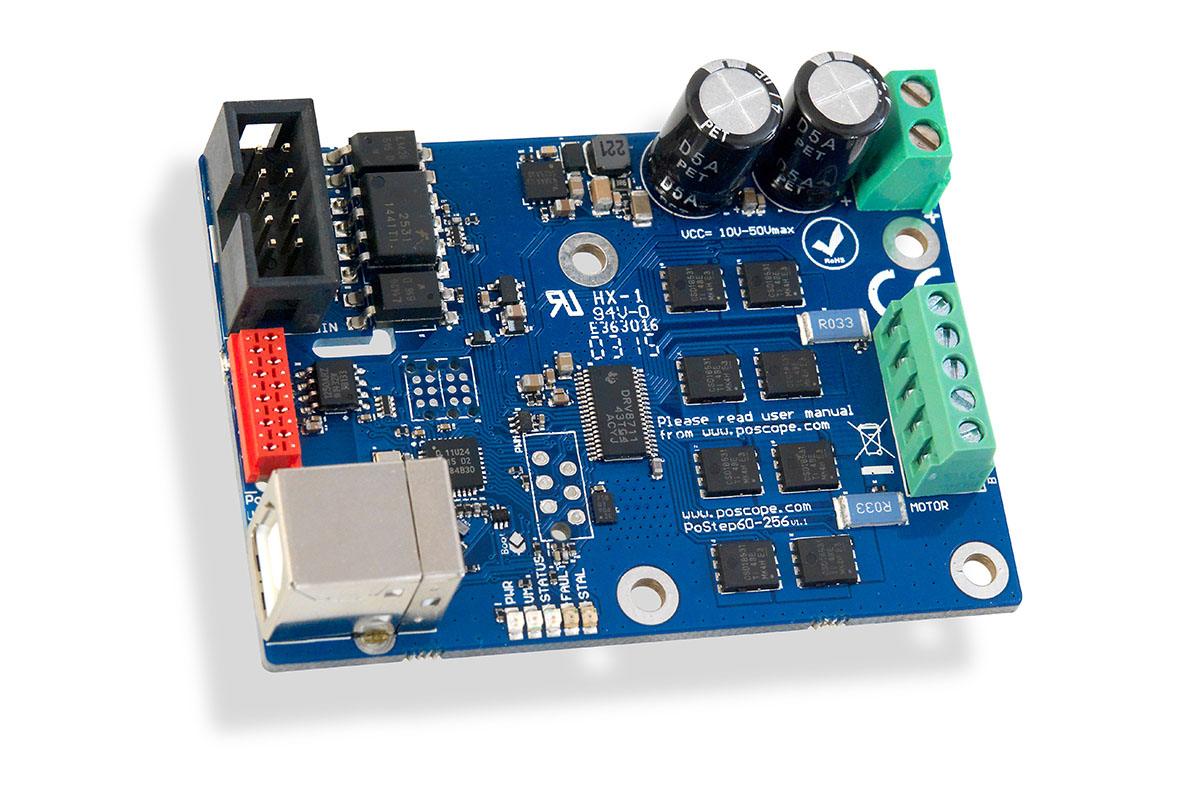
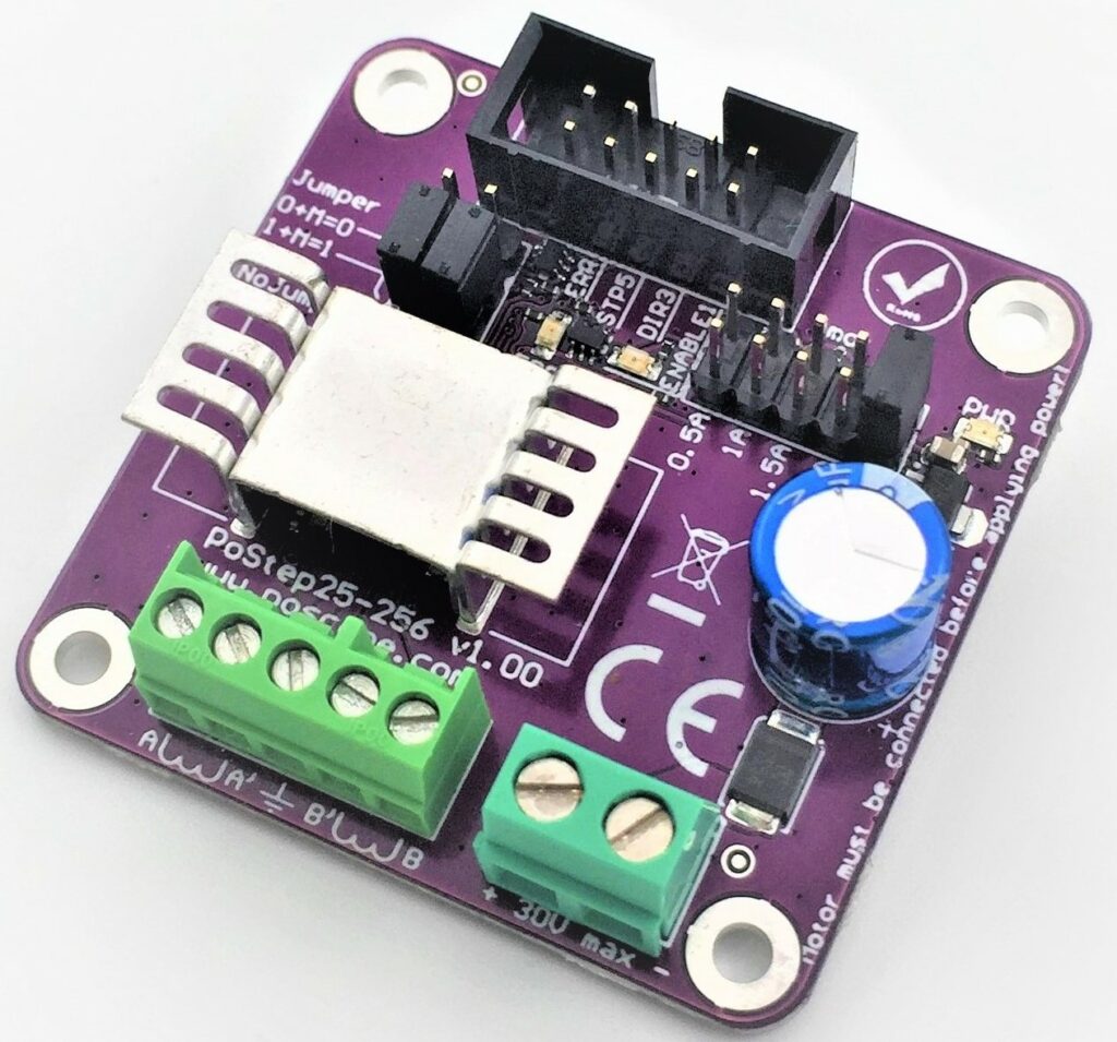
Stepper Motor Driver Wiring
Proper wiring is crucial for the effective operation of a stepper motor driver. Understanding how to correctly connect a stepper motor driver ensures that the motor functions efficiently and reliably, minimizing the risk of damage or performance issues. This chapter will guide you through the essentials of stepper motor driver wiring, including the key connections and considerations.
Power Supply Connections
The first step in wiring a stepper motor driver is connecting the power supply. Stepper motor drivers typically require a DC power supply to operate. The voltage and current ratings of the power supply should match the specifications of the driver and the stepper motor. It’s important to connect the positive and negative terminals of the power supply to the corresponding input terminals on the driver. Ensure that the power supply provides adequate current for the motor to avoid underperformance or overheating.
Motor Connections
Next, connect the stepper motor to the driver. Stepper motors usually have four, six, or eight wires, depending on their type (bipolar or unipolar). For bipolar stepper motors, you will need to connect the motor’s two coil pairs to the driver’s output terminals. For unipolar stepper motors, the connections involve attaching the center taps of the coils to the driver’s output terminals, along with the coil ends. Refer to the motor and driver documentation for the correct wiring diagram.
Control Signal Connections
The control signals from a microcontroller or control system need to be wired to the stepper motor driver. These signals typically include step (pulse) and direction signals. The step signal determines when the motor should take a step, while the direction signal indicates the direction of rotation. Connect these signals from the control system to the respective input terminals on the driver. In some drivers, additional signals like enable or reset may also need to be connected, depending on the driver’s features.
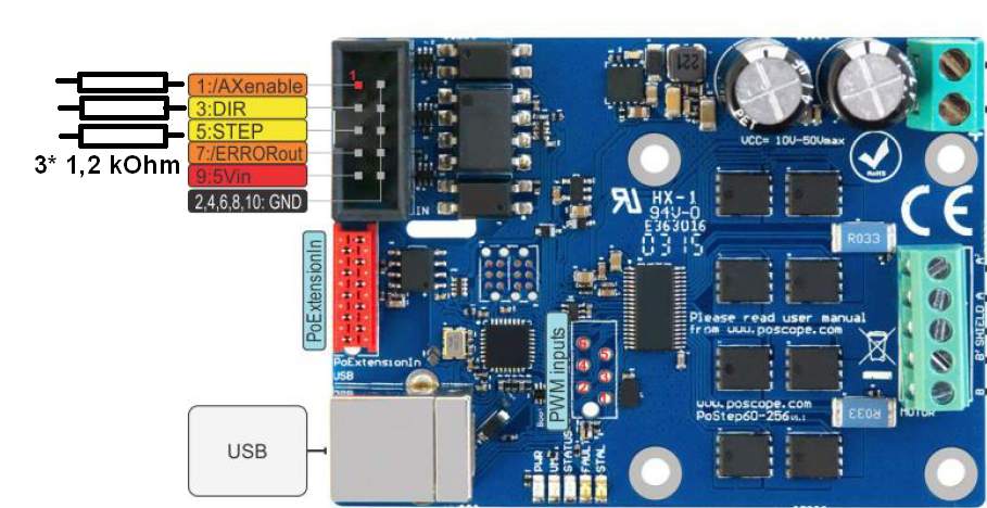
Grounding and Safety
Proper grounding is essential for stable operation and to prevent electrical interference. Connect the ground terminal of the power supply to the ground terminal on the stepper motor driver. Additionally, ensure that the ground of the control system is connected to the driver’s ground. This common grounding helps to prevent noise and signal errors. Always follow safety precautions, such as powering off the system before making connections, to avoid electrical hazards or damage to components.
Testing and Troubleshooting
After wiring, it’s important to test the connections to ensure everything is functioning correctly. Power up the system and use a multimeter to check for correct voltage levels and continuity. If the stepper motor does not operate as expected, verify all connections against the wiring diagram and check for any loose or incorrect wiring. Troubleshooting steps may also involve checking the driver’s settings and configurations to ensure they match the motor specifications.
In summary, correct wiring of a stepper motor driver involves connecting the power supply, motor, and control signals while ensuring proper grounding and safety. Following these steps carefully will help you achieve reliable and efficient operation of your stepper motor system.
Stepper Motor Driver with Modbus
Integrating a stepper motor driver with Modbus communication protocol enhances the versatility and control of stepper motor systems. Modbus is a widely used communication protocol in industrial automation, offering robust data exchange between devices over serial lines. In this chapter, we’ll explore how stepper motor drivers can be interfaced with Modbus, the benefits of this integration, and how to set it up effectively.
Understanding Modbus Protocol
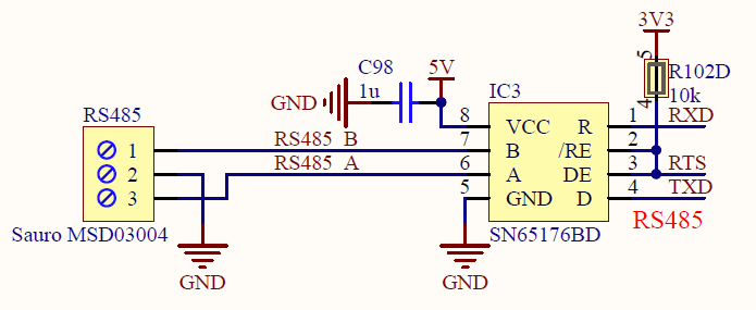
Modbus is a serial communication protocol that allows multiple devices to communicate over a network. It supports two primary modes: Modbus RTU (Remote Terminal Unit) and Modbus TCP (Transmission Control Protocol). Modbus RTU operates over serial communication lines like RS-232 or RS-485, while Modbus TCP uses Ethernet networks. For stepper motor drivers, Modbus RTU is commonly used due to its simplicity and effectiveness in industrial environments.
Benefits of Modbus Integration
Integrating a stepper motor driver with Modbus provides several advantages:
- Centralized Control: Modbus allows for centralized control of multiple stepper motors from a single master device, such as a PLC (Programmable Logic Controller) or a computer. This is particularly useful in complex systems where precise coordination between motors is required.
- Remote Monitoring: With Modbus, you can remotely monitor and control stepper motors, enabling real-time adjustments and diagnostics without physical access to the hardware.
- Scalability: Modbus networks can easily be expanded by adding more devices. This scalability makes it ideal for systems that require the integration of additional stepper motors or other automation components in the future.
Setting Up Modbus Communication
To set up a stepper motor driver with Modbus, follow these steps:
- Verify Compatibility: Ensure that the stepper motor driver supports Modbus communication. Check the driver’s documentation for details on Modbus settings and supported communication modes.
- Connect the Hardware: For Modbus RTU, connect the driver’s Modbus terminals to the Modbus network using RS-485 cables. Ensure proper wiring for the data lines (A and B) and ground. For Modbus TCP, connect the driver to the Ethernet network.
- Configure the Driver: Access the driver’s configuration settings through its software or hardware interface. Set the Modbus address, baud rate, and other communication parameters according to the Modbus network requirements and the driver’s specifications.
- Program the Master Device: Program the master device (e.g., PLC or computer) to communicate with the stepper motor driver using Modbus commands. This involves sending specific Modbus function codes to control the motor’s movement, speed, and other parameters.
- Test the Setup: After configuration, test the communication between the master device and the stepper motor driver. Verify that commands are correctly received and executed by the driver, and that feedback from the driver is accurately reported back to the master device.
Troubleshooting and Maintenance
During integration, you may encounter issues such as communication errors or unexpected motor behavior. Common troubleshooting steps include checking wiring connections, verifying Modbus addresses and parameters, and ensuring that the master device is correctly programmed. Regular maintenance of the Modbus network, including checking for cable integrity and signal interference, helps ensure long-term reliability.
In conclusion, integrating a stepper motor driver with Modbus offers significant benefits in terms of centralized control, remote monitoring, and system scalability. By understanding the Modbus protocol, setting up the communication correctly, and performing regular maintenance, you can enhance the functionality and performance of your stepper motor systems.
Read also:
- Mastering CNC Control: A Guide to Ethernet I/O Controllers, PoKeys57CNC Pinout, Mach3 Limit Switches, and CNC Wiring
- A Comprehensive Guide to Mach4 CNC Controller, PoKeys, Mach4 Motion Controller, and Probing Techniques
- Understanding Key Components in Modern Automation: Slip Ring Tests, 8 Channel Relay Modules, Automation Control Devices, and Programmable Relays
Conclusion
In this guide, we’ve explored the fundamental aspects of stepper motor drivers, from their basic functions to advanced integration techniques. We began by understanding what a stepper motor driver is and why it is essential for precise motor control. We then delved into the inner workings of a stepper motor driver, highlighting how it converts control signals into accurate mechanical movements.
We also examined the crucial process of stepper motor driver wiring, detailing the connections needed for power supply, motor, and control signals, and emphasizing the importance of proper grounding and safety measures. Lastly, we discussed the integration of stepper motor drivers with the Modbus communication protocol, showcasing how this setup enhances control, monitoring, and scalability in complex systems.
By comprehending the operation of stepper motor drivers, mastering their wiring, and effectively integrating them with Modbus, you can achieve precise, reliable, and efficient performance in your applications. Whether you’re a hobbyist or a professional, this knowledge will empower you to optimize your stepper motor systems and meet your specific operational needs.
We hope this guide has provided valuable insights and practical advice to help you work with stepper motor drivers effectively.